Difference between revisions of "Installation and Integration/ActionItems/Cables"
| (55 intermediate revisions by the same user not shown) | |||
| Line 1: | Line 1: | ||
= Cable routing decision = | = Cable routing decision = | ||
| + | |||
| + | There are currently two potential options: | ||
| + | |||
| + | 1) Route the cables from the lower APA up "along" the upper APA frame. | ||
| + | |||
| + | 2) Route the cables down to the floor of the cryostat all the way to the walls and up the walls. | ||
== Information on current status == | == Information on current status == | ||
| − | ===APA Dimensions=== | + | ===Cables and APA Dimensions=== |
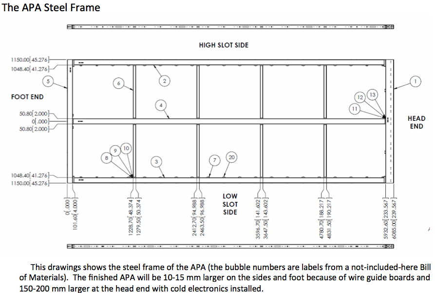
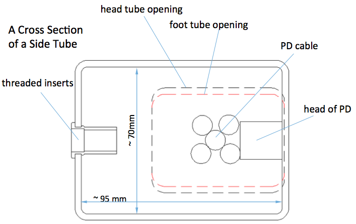
| − | * '''APA opening dimensions (usable): 44mm x 63 mm = 2772mm<sup>2''' (constrained by foot opening -> Cannot be larger to have enough space for glueing/soldering wires on the foot boards) | + | * '''APA opening dimensions (usable): 44mm x 63 mm = 2772mm<sup>2''' (constrained by foot tube opening -> Cannot be larger to have enough space for glueing/soldering wires on the foot boards) |
| − | Actual dimensions: 70mm x 95mm (see below for drawings) | + | Actual dimensions: 70mm x 95mm = 6650mm<sup>2</sup> (see below for drawings) |
| + | |||
| + | * '''Occupancy''': -> 1891.2mm<sup>2</sup> (with connectors: 3681.4mm<sup>2</sup> ) | ||
| − | * ''' | + | [[File:arrangement.png | 700px]] |
| − | ** PD: PD | + | [[File:trial.png | 700px]] |
| + | |||
| + | ** '''PD: = 441.8mm<sup>2</sup>''' : | ||
| + | ***From Dave/Leon: | ||
| + | **** PD cables have spec diameter of 6.9mm, but in reality, due to uniformities, they are between 7.5 and 8 mm => area = 44.2mm<sup>2</sup> | ||
| + | **** 5 PD cables = 5 x 44.2mm<sup>2</sup> = 220.4mm<sup>2</sup> | ||
| + | **** 10 PD cables= 441.8mm<sup>2 </sup> | ||
| + | **** NOTE: the PD heads are 18.5mmx18.5mm = 342.25mm<sup>2 </sup>, but it's NOT included here since it takes space only inside the tube and doesn't not go through the foot tube opening | ||
| + | **** '''PD cables''' (Cat6): 9-10 mm diameter + PD head (18.5mm x 18.5mm). 5 cables per APA -> 10 cables in upper APA | ||
| + | [[File:PC_cable.png|200px]] | ||
| + | **Support bar = 13mmx40mm = 520mm<sup>2</sup>, since it can be added after the cable routing, it's NOT included in total | ||
| + | ** Potential CE cables, 20 data cables + 20 LV cables, but only '''10 of each''' to pass by APA sides | ||
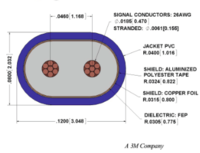
| + | *** Data cables: Width=21.4mm, Thick=4.06mm = 86.88mm<sup>2</sup> | ||
| + | *** Data cable connectors: Width = 26.04mm, Thick: smaller than the cable bundle thickness = 105.72mm<sup>2</sup> | ||
| + | *** LV cables: Width: 22.86mm, Thick: 2.54mm = 58.06mm<sup>2</sup> | ||
| + | *** LV cable connectors: Width=24.33mm, Thick=8.97mm = 218.24mm<sup>2</sup>: | ||
| + | *** If bundled 10 Data + 10 LV per APA side= '''1449.4mm<sup>2</sup>''' (with connectors = 3239.6mm<sup>2</sup>) | ||
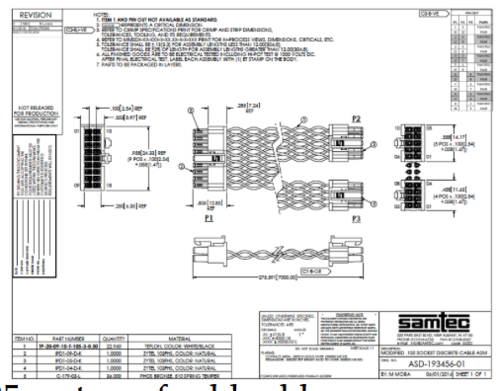
| + | * '''Cold cables''': Max length = 25m (validated length for Gore), 20 CE cable pairs per APA (can they be split for each side of APA frame? -> 10 CE cable pairs per tube?) | ||
| + | -> CE cable pairs = blue data cables (26mm wide connector) + black-white LV cables (16mm wide connector) | ||
| + | [[File:cables.png]] | ||
| − | + | [[File:cable_drawing.png | 500px]][[File:cable_drawing2.png| 200px]] [[File: lv_cable.png | 500px]] | |
| − | + | ** '''Bias Cables: = 34.3mm<sup>2</sup>''' : | |
| + | *** 7 Bias Cables (BC) | ||
| + | *** BC (RG316): 2.5mm OD = 4.9mm<sup>2</sup> | ||
| + | *** BC connectors (SHV plug): OD 14.5mm = 165.13mm<sup>2</sup> | ||
| − | + | * Missing 144mm<sup>2</sup>! That's 2 LV cable connector areas. Which means that if we extract the bundle from the cold cables not in one big bundle of connectors, it might be doable. | |
| − | |||
| − | + | '''Drawings''': | |
| − | + | [[File:APA.png]] | |
| − | + | [[File:xsec.png]] | |
| − | + | [[File:PD_cables.jpeg | 500px]] [[File: PD_Cables_2.jpeg |500px]] | |
| − | |||
| − | [[File: | ||
===Cable routing plan for protoDUNE === | ===Cable routing plan for protoDUNE === | ||
| Line 35: | Line 62: | ||
[[File:routing2.png|500px]][[File:routing1.png|500px]] | [[File:routing2.png|500px]][[File:routing1.png|500px]] | ||
| + | |||
| + | ===Cable Testing results=== | ||
| + | |||
| + | Cables have been tested at BNL and J. Kierstead has prepared a summary document available here [[cabletesting]] | ||
== Concerns and questions == | == Concerns and questions == | ||
| Line 47: | Line 78: | ||
* Is there anyway we can attached the cables on the cryostat wall? At the moment there is no mechanical device on the inner cryostat membrane. The space between APA and membrane is ~15cm. Need to take the weight of the cables into account in this design solution. | * Is there anyway we can attached the cables on the cryostat wall? At the moment there is no mechanical device on the inner cryostat membrane. The space between APA and membrane is ~15cm. Need to take the weight of the cables into account in this design solution. | ||
| + | |||
| + | ===Email notes from the Grounding and Shielding Group=== | ||
| + | Q: What are the consequences if we route both cold electronics cables (data and power) on the floor/wall? What shielding is required? | ||
| + | R1: As the copper data cable becomes longer, the high speed signal (~1Gbps ) will become degraded and we need to do further testing to make sure transmission of data is OK over the greater length. | ||
| + | R2: Yes, we need to do more, but BNL has already looked at 30m lengths of the candidate cable and they see good results from that single cable. It seems very unlikely to me that additional shielding would be needed in any case. If the cable is too marginal at the longer distance the first order correction would be a slightly larger cable size (more copper and more space improves the performance). However, I suspect that you are already planning to have significant margin to accept a somewhat larger cable plant so this probably not an issue. | ||
| + | R1: As the power data gets longer, there will be more IR power dropped in the cable. Again, this is something we need to calculate/study based upon worst case length. | ||
| + | R2: This may imply using a larger gauge wire for the longer cables but the increase in cross section would be modest from your point of view. | ||
| + | |||
| + | |||
| + | Q: Can we route the power cables in the APA tubes, next to the Photon Detector cables? If yes, what requirements on shielding? What about "loops" between the power cable going up the tube and the data cables going on the floor/wall? | ||
| + | R1: I think you heard that the PD system engineer would prefer that the APA power cables are not routed next to the PD cables. If they are, my belief is that we definitely need to provide shielding of the power cables. The current power cables selected by BNL do not include an overall shield. In any event, it is something we would want to study. We don’t expect a “loop” to be caused by routing the power and signal cables along different paths. | ||
| + | R2: I would concur and would also expect that you should assume, at least for now, that all the power cables are shielded (and thus slightly larger cross section than the present design). | ||
| + | |||
| + | |||
| + | Q: If we decide to route them along the outside of the APA frames (e.g. between the frames), what are you input about shielding for both types and the noise on wires? | ||
| + | R1: I believe the power cables should be shielded. The data cables are individually shielded; system studies can be done to see if additional shielding is required. | ||
| + | An effective shield might also include different connector choices. | ||
| + | R2: If I understand the idea of routing along the outside of the APA frame that topology would imply both distorting the E field in a way that would require some sort of additional correcting structure on the APA combined with a loss of sensitivity over a significantly larger "gap" region between APAs. I suspect that this would be fairly violently objected to by both the APA and physics groups - you should check with them before spending much more effort on this option. I agree with Terri that from the point of view of G&S it would at worst only be a question of perhaps some additional shielding. | ||
| + | |||
| + | ------ | ||
| + | My feeling is that routing the cables alone the bottom and sides is the only viable alternative. I am not too concerned about either voltage drop or cable attenuation because both can be solved with larger cables. There is a potential problem for long power cables without remote sense on the front end boards. This is clearly not an insurmountable problem but it requires an integrated design effort between the WIB and front end board designers. | ||
| + | |||
| + | Your question prompted me to spend some time reviewing both the 35 ton data and the results from the Talbo photon system tests at Fermilab. The design of the 35 ton readout was based on separating the APA and photon systems in frequency space. The photon system is fairly insensitive to 2 MHz signals and they can easily be filtered out with a digital filter. The APA readout has very strong attenuation above a few MHz. This did not work out in the 35 ton system. There was a strong 19 MHz signal in the photon system that appears to be associated with the APA system. The source of this signal is not yet understood. For DUNE, there will be a 50 MHz clock signal that is likely to be in phase over the entire detector as well as other medium frequency signals in the front end digital system. There will likely be quite a bit of power in the 50 MHz signal and it is in the main band of the photon digitizers. Separation in frequency space should work but we need to pay attention to isolating the digital part of the APA system from photon system. Thus, routing the photon cables inside the frames of the APA along the shortest path to the readout port while routing the APA cables along the cryostat floor is the best approach. | ||
| + | The photon cables need to be at least shielded from the APA cables at the feed through ports. A separate port for the photon system would be even better. Note tat the photon system needs no additional cables since the bias is provided on the readout cables. | ||
| + | The APA system is all digital and it is really not a difficult issue to run longer cables as long as the system is properly designed. | ||
| + | The 35 ton system has shown that the cable system is a very important part f the detector electronics. The DUNE system needs both careful design and thorough testing in a prototype. | ||
== Group interface == | == Group interface == | ||
Latest revision as of 15:19, 27 March 2017
Contents
Cable routing decision
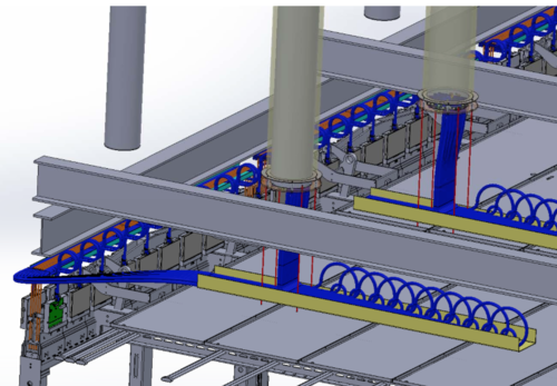
There are currently two potential options:
1) Route the cables from the lower APA up "along" the upper APA frame.
2) Route the cables down to the floor of the cryostat all the way to the walls and up the walls.
Information on current status
Cables and APA Dimensions
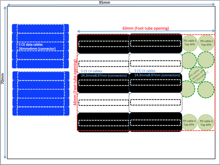
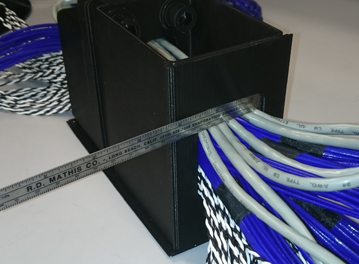
- APA opening dimensions (usable): 44mm x 63 mm = 2772mm2 (constrained by foot tube opening -> Cannot be larger to have enough space for glueing/soldering wires on the foot boards)
Actual dimensions: 70mm x 95mm = 6650mm2 (see below for drawings)
- Occupancy: -> 1891.2mm2 (with connectors: 3681.4mm2 )
- PD: = 441.8mm2 :
- From Dave/Leon:
- PD cables have spec diameter of 6.9mm, but in reality, due to uniformities, they are between 7.5 and 8 mm => area = 44.2mm2
- 5 PD cables = 5 x 44.2mm2 = 220.4mm2
- 10 PD cables= 441.8mm2
- NOTE: the PD heads are 18.5mmx18.5mm = 342.25mm2 , but it's NOT included here since it takes space only inside the tube and doesn't not go through the foot tube opening
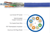
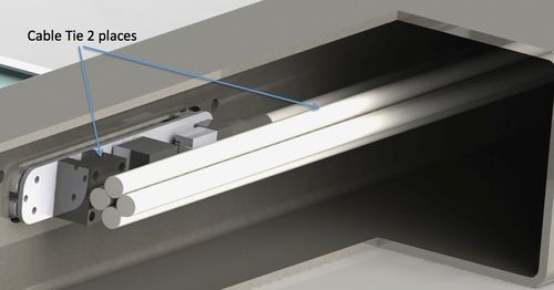
- PD cables (Cat6): 9-10 mm diameter + PD head (18.5mm x 18.5mm). 5 cables per APA -> 10 cables in upper APA
- From Dave/Leon:
- PD: = 441.8mm2 :
- Support bar = 13mmx40mm = 520mm2, since it can be added after the cable routing, it's NOT included in total
- Potential CE cables, 20 data cables + 20 LV cables, but only 10 of each to pass by APA sides
- Data cables: Width=21.4mm, Thick=4.06mm = 86.88mm2
- Data cable connectors: Width = 26.04mm, Thick: smaller than the cable bundle thickness = 105.72mm2
- LV cables: Width: 22.86mm, Thick: 2.54mm = 58.06mm2
- LV cable connectors: Width=24.33mm, Thick=8.97mm = 218.24mm2:
- If bundled 10 Data + 10 LV per APA side= 1449.4mm2 (with connectors = 3239.6mm2)
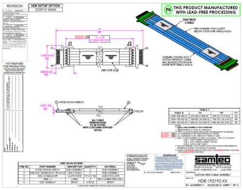
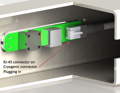
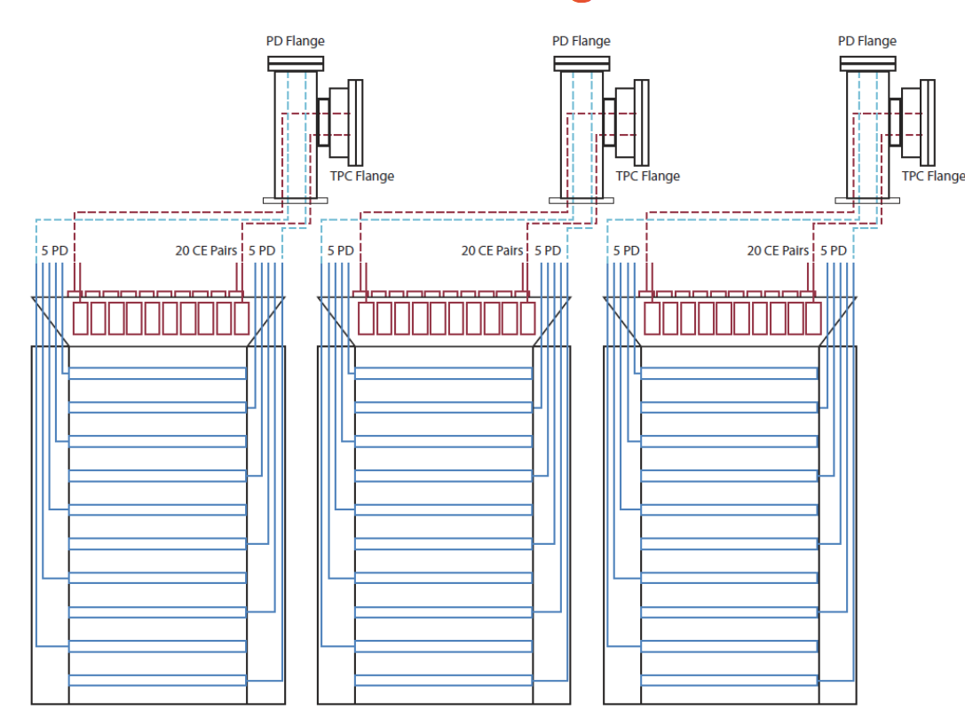
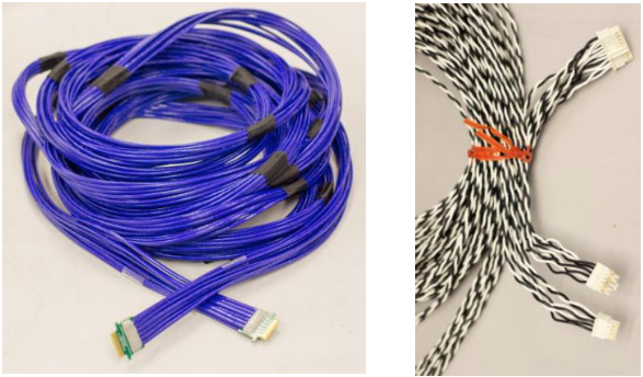
- Cold cables: Max length = 25m (validated length for Gore), 20 CE cable pairs per APA (can they be split for each side of APA frame? -> 10 CE cable pairs per tube?)
-> CE cable pairs = blue data cables (26mm wide connector) + black-white LV cables (16mm wide connector)
- Bias Cables: = 34.3mm2 :
- 7 Bias Cables (BC)
- BC (RG316): 2.5mm OD = 4.9mm2
- BC connectors (SHV plug): OD 14.5mm = 165.13mm2
- Bias Cables: = 34.3mm2 :
- Missing 144mm2! That's 2 LV cable connector areas. Which means that if we extract the bundle from the cold cables not in one big bundle of connectors, it might be doable.
Drawings:
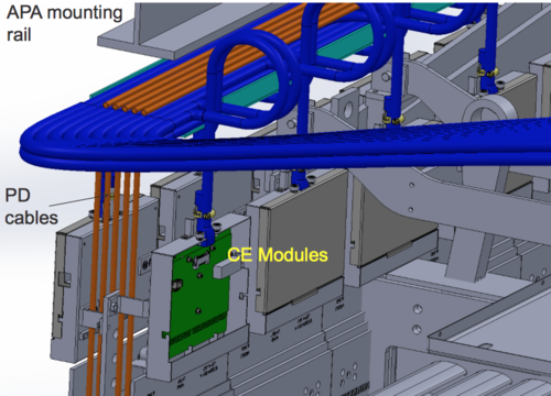
Cable routing plan for protoDUNE
Cable Testing results
Cables have been tested at BNL and J. Kierstead has prepared a summary document available here cabletesting
Concerns and questions
- How difficult is it to bring the cables up (in or on?) the APA frame? How long are the cables? What type of access we need to pass the cables through?
- Are there any mechanical difficulties to pass the cables up the APA frame? Weight? Space?
- Grounding and Shiedling: Can we bundle the cables together? Do we need mechanical/electrical separations in the APA frame?
- If we go along the cryostat wall, we need longer cables. What is the impact of longer cables on readout? Procurement?
- Is there anyway we can attached the cables on the cryostat wall? At the moment there is no mechanical device on the inner cryostat membrane. The space between APA and membrane is ~15cm. Need to take the weight of the cables into account in this design solution.
Email notes from the Grounding and Shielding Group
Q: What are the consequences if we route both cold electronics cables (data and power) on the floor/wall? What shielding is required? R1: As the copper data cable becomes longer, the high speed signal (~1Gbps ) will become degraded and we need to do further testing to make sure transmission of data is OK over the greater length. R2: Yes, we need to do more, but BNL has already looked at 30m lengths of the candidate cable and they see good results from that single cable. It seems very unlikely to me that additional shielding would be needed in any case. If the cable is too marginal at the longer distance the first order correction would be a slightly larger cable size (more copper and more space improves the performance). However, I suspect that you are already planning to have significant margin to accept a somewhat larger cable plant so this probably not an issue. R1: As the power data gets longer, there will be more IR power dropped in the cable. Again, this is something we need to calculate/study based upon worst case length. R2: This may imply using a larger gauge wire for the longer cables but the increase in cross section would be modest from your point of view.
Q: Can we route the power cables in the APA tubes, next to the Photon Detector cables? If yes, what requirements on shielding? What about "loops" between the power cable going up the tube and the data cables going on the floor/wall?
R1: I think you heard that the PD system engineer would prefer that the APA power cables are not routed next to the PD cables. If they are, my belief is that we definitely need to provide shielding of the power cables. The current power cables selected by BNL do not include an overall shield. In any event, it is something we would want to study. We don’t expect a “loop” to be caused by routing the power and signal cables along different paths.
R2: I would concur and would also expect that you should assume, at least for now, that all the power cables are shielded (and thus slightly larger cross section than the present design).
Q: If we decide to route them along the outside of the APA frames (e.g. between the frames), what are you input about shielding for both types and the noise on wires?
R1: I believe the power cables should be shielded. The data cables are individually shielded; system studies can be done to see if additional shielding is required.
An effective shield might also include different connector choices.
R2: If I understand the idea of routing along the outside of the APA frame that topology would imply both distorting the E field in a way that would require some sort of additional correcting structure on the APA combined with a loss of sensitivity over a significantly larger "gap" region between APAs. I suspect that this would be fairly violently objected to by both the APA and physics groups - you should check with them before spending much more effort on this option. I agree with Terri that from the point of view of G&S it would at worst only be a question of perhaps some additional shielding.
My feeling is that routing the cables alone the bottom and sides is the only viable alternative. I am not too concerned about either voltage drop or cable attenuation because both can be solved with larger cables. There is a potential problem for long power cables without remote sense on the front end boards. This is clearly not an insurmountable problem but it requires an integrated design effort between the WIB and front end board designers.
Your question prompted me to spend some time reviewing both the 35 ton data and the results from the Talbo photon system tests at Fermilab. The design of the 35 ton readout was based on separating the APA and photon systems in frequency space. The photon system is fairly insensitive to 2 MHz signals and they can easily be filtered out with a digital filter. The APA readout has very strong attenuation above a few MHz. This did not work out in the 35 ton system. There was a strong 19 MHz signal in the photon system that appears to be associated with the APA system. The source of this signal is not yet understood. For DUNE, there will be a 50 MHz clock signal that is likely to be in phase over the entire detector as well as other medium frequency signals in the front end digital system. There will likely be quite a bit of power in the 50 MHz signal and it is in the main band of the photon digitizers. Separation in frequency space should work but we need to pay attention to isolating the digital part of the APA system from photon system. Thus, routing the photon cables inside the frames of the APA along the shortest path to the readout port while routing the APA cables along the cryostat floor is the best approach. The photon cables need to be at least shielded from the APA cables at the feed through ports. A separate port for the photon system would be even better. Note tat the photon system needs no additional cables since the bias is provided on the readout cables. The APA system is all digital and it is really not a difficult issue to run longer cables as long as the system is properly designed. The 35 ton system has shown that the cable system is a very important part f the detector electronics. The DUNE system needs both careful design and thorough testing in a prototype.
Group interface
- Inst.& Int.: Roxanne, Bill, Marvin
- APA: PSL (Lee and Dan) and Daresbury (Jo)
- PD: David, Leon and Gary
- CE: Matt
Potential testing sites
- Ash River (contact: Bill)
- Daresbury (contact: Jo)
