Difference between revisions of "Installation and Integration"
JimStewart (talk | contribs) |
JimStewart (talk | contribs) |
||
| Line 6: | Line 6: | ||
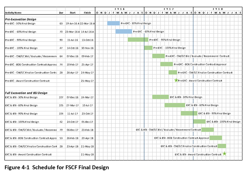
[[Image:CF-design-schedule.png |800px]] | [[Image:CF-design-schedule.png |800px]] | ||
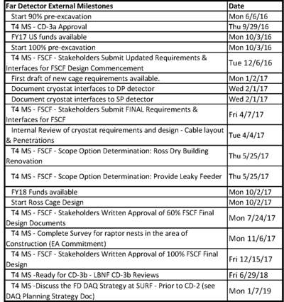
| − | [[Image:InterfaceMilestones-CF-v2.png | | + | The table of external milestones connected to the CF design process is listed below: |
| + | |||
| + | [[Image:InterfaceMilestones-CF-v2.png |400px]] | ||
===Key Documents=== | ===Key Documents=== | ||
Revision as of 18:41, 10 October 2016
Contents
Integration and Installation
Far Detector Integration
The interface between the Conventional Facilities and the cryogenic/cryostat with the Far Detector are a major component of the integration group for DUNE.
The table of external milestones connected to the CF design process is listed below:
Key Documents
- LBNF BSI Pre-Excavation 60% Final Design Submission
- Comprehensive Logistics Plan
- LBNF EXC Pre-Excavation 60% Final Design Submission
Logistics
The general plan for how materials will be transported to and within SURF is found in the SURF Logistics Assumptions document.
The Comprehensive Logistics Plan describes in some detail how the shaft usage will need to be planned. It also contains on page 9 the description of the detector needs which DUNE defined for the logistics study.
3.1.3 Time Projection Chambers The cryostat time projection chamber (TPC; see Figure 6) comprises the following components:
- Anode Plane Assemblies (APAs) – 150 ea. 2.3m × 6.3m × 0.1m
- Four APAs per shipping container (see Figure 7)
- Estimated weight of 3,600kg per container
- Cathode Plane Assemblies (CPAs) – 200 ea.
- 2.3m × 3m (1400 m2)
- Four CPAs per shipping container
- Field cage (2,000m2)
- Readout electronics and racks – 75 ea.
- High V oltage (HV) system
The main elements are shipped in containers 1.3m × 2.8m × 7.3m (APA’s) and 0.5m × 2.5m × 3.8m (CPA’s) and 0.6m × 0.8m × 2.1m (racks). Most items will be configured in skid-size containers.
Other Key documents and events related to the SURF logistics are:
Surface Facilities
Ross Shaft
The far site conventional facilities is using the information from the Drift Study for referencing the maximum size objects that need to be accommodated by the surf infrastructure.
Underground facilities
Interface Management
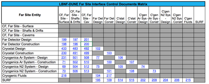
The interfaces between Conventional Facilities and the Far Detector are documented through a series of Interface Control Documents that are agreed upon by both LBNF and DUNE. The ICDs themselves generally only identify the interface and then refer to a separate key document to describe and define the interface.
LBNF Systems Engineering webpage for interface management
Interface Control Documents
- CF Far Site Surface <--> Far Detector Design
- CF Far Site Shafts and Drifts <--> Far Detector Design
- CF Far Site Caverns <--> Far Detector Design
- CF Far Site Surface <--> Far Detector Construction
- CF Far Site Shafts and Drifts <--> Far Detector Construction
- CF Far Site Caverns <--> Far Detector Construction


